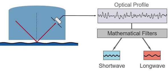
It all started with LW and SW in the early 1990s. BYK-Gardner´s well-known wave-scan analyzes waviness based on wavelength range and its intensity.
Picture 1: Waviness principle LW - SW
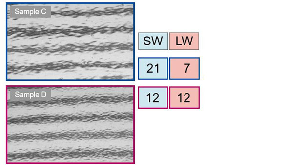
The LW value integrates waviness in the range of 1.2 - 12 mm and the SW value sums up fine textures in the range of 0.3 - 1.2 mm.
Picture 2: Sample measurements LW - SW
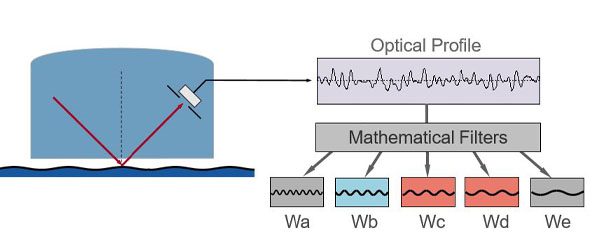
As material and process parameters changed, these integrated parameters were not always sufficient to differentiate various surface appearances.
Picture 3: Five new wavelength ranges
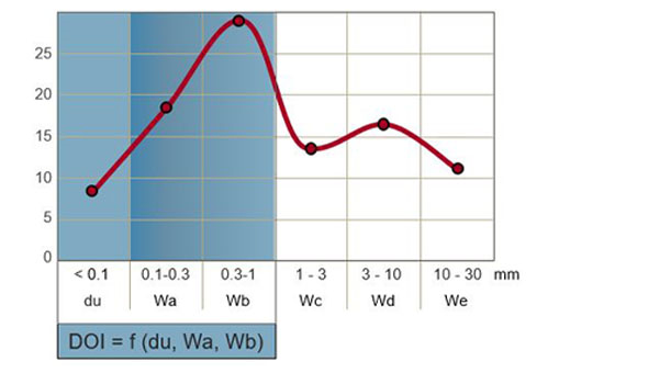
Consequently, in 2001 the next generation, wave-scan DOI was introduced measuring five wavelength ranges as well as the distinctness of image. These six measurement parameters are graphed and called a “structure spectrum”, which is an ideal guide for trouble shooting and optimizing surface appearance based on material or application influencers.
Picture 4: DOI principle of wave-scan plus structure spectrum
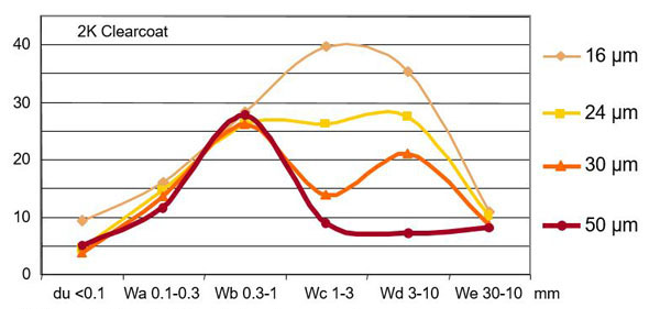
Pciture 5: Film build and structure spectrum
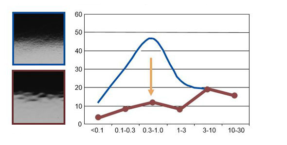
Picture 6: Primer roughness - after sanding
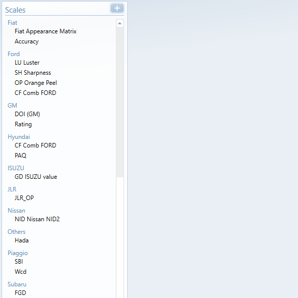
To keep it simple for QC control and management reports 1- or 2-dimensional scales are used. Additionally to LW and SW, OEM specific scales with different target values and tolerances were developed over the years.
Picture 7: Overview OEM scales - selection in smart-chart
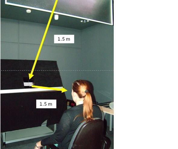
In 2012, a new approach was initiated within the VW/Audi group and was first presented at our BYK-Gardner User Meeting in 2013.
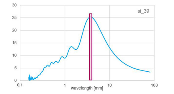
Since then several visual studies were conducted and it became obvious that observers can distinguish samples based on its dominating wavelengths. In order to determine a specific waviness size, the optical profile of the wave-scan measurement needs to be analyzed with a so-called Fast Fourier Transformation, which is in simple words, a structure spectrum with much higher resolution.
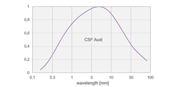
The results are weighted according to the VW / Audi study to simulate an observation distance of 1.5 m.
Picture 8: Visual evaluation at Audi
Picture 9: FFT
Picture 10: CSF
Picture 11: FFT weighted
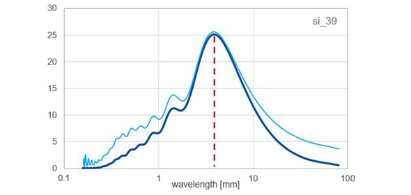
The result is up to four new scales:
- Dominant LW wavelength
and its maximum amplitude - Dominant SW wavelength
and its maximum amplitude

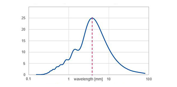
Highest intensity of dominant wavelenght > 2.4 mm:
- Dominant LW = 4.6 mm
- Dominant LW intensity = 25.1
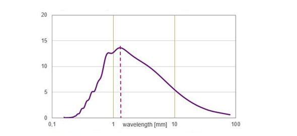
Highest intensity of dominant wavelenght < 2.4 mm:
- Dominant SW = 1.3 mm
- Dominant SW intensity = 13.6
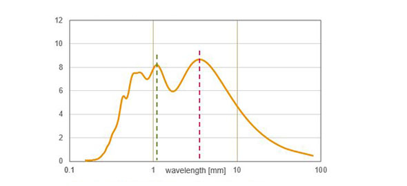
Two dominant wavelengths:
- Dominant LW = 4.4 mm
- Dominant LW intensity = 8.6
- Dominant SW = 1.3 mm
- Dominant SW intensity = 8.2
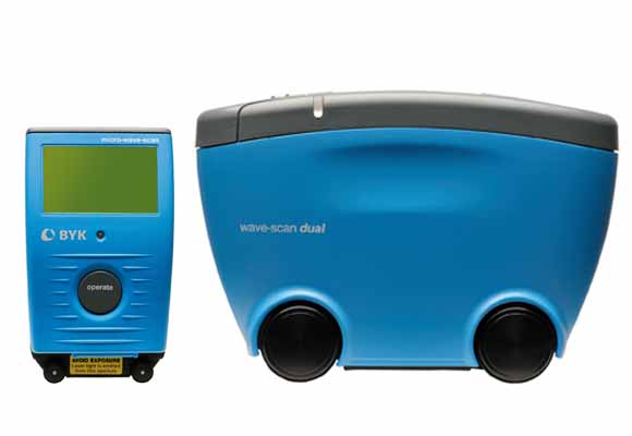
Curious? The new firmware is free of charge and available for download in the smart-chart package under:
